3M
This page is a work in progress!
Contents
3M Brand
From 1969 to 2007, 3M produced signals and adapters designed to enhance signal visibility to both drivers and pedestrians. Their most iconic and well-known product is the M-131.
Products
Full Vehicle Signals (12")
M-123 Programmable Visibility Prototype Signal
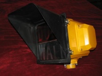
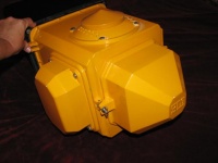
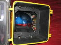
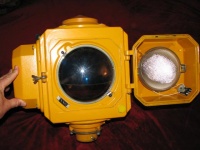
The M-123 was the first traffic signals ever made by 3M. They were most likely made a few years before 1969. It's original purpose was to have "high visibility"; more fully-lit and easier-to-see indications. It could also be used for "programmable visibility", which means the viewing area of the signal can be limited down to single lane.
This signal was a prototype. It is known as an early version of the M-131. The M-131 signals are nearly identical to these; 3M sold them to cities that liked the idea and wanted to test them out. 3M tested them and made improvements as they saw fit. Finally, 3M released their final product as the all-new M-131 signal and began expanding their product line.
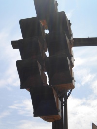
The main visible difference is that the rear lamp door/housing was cone-shaped, unlike the M-131's more faceted version The M-123's doors had the 2 hinges on top and the 2 wingnuts on the bottom instead of on either side. M-123s didn't have latches to secure the lenses, so they were prone to falling out if the door was opened. The tilt adjusters were on the front corners of the signal housing instead of on the connector. Finally, they were sand-casted, and somewhat heavier than M-131s.
Lenses
These were available with the following lenses:
- Red Ball
- Yellow Ball
- Green Ball
- Green Arrow
M-131 Programmable Visibility Signal
Overview, Construction, Lenses, Masking Process, Uses/Advantages, Disadvantages
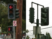
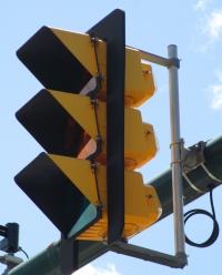
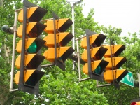
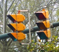
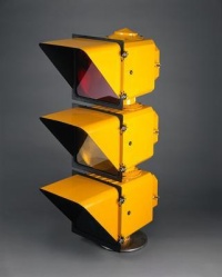
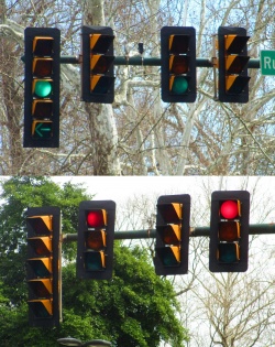
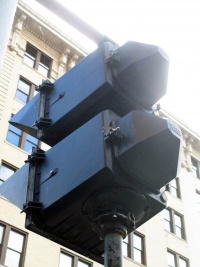
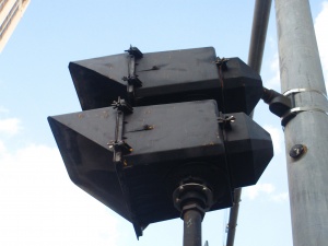
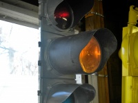
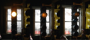
3M, the same company that makes well-known everyday products such as Scotch tape, entered the traffic control industry in 1969 with High-Visibility signals. These lights were unlike any other at the time in both design and operation. The most noticeable features are the square lenses and futuristic-looking housing. The also had special capabilities, such as High Visibility (giving a fuller, clearer indication) and, most notably, Programmable Visibility (being able to limit the viewing area to as little as a single lane). After modifying the M-123 prototype signal, 3M released the M-131 in 1969 and produced them until 2007 with only a few changes.
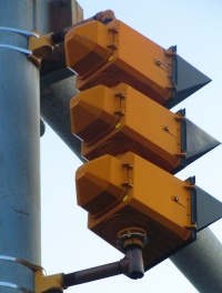
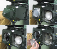
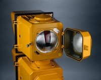
On the back of a 3M signal, there is a door; while most signals only have a front door, these signals are so large it is much easier to have two. This door serves as the access point and housing of the bulb. The bulb is a PAR 46 lamp, which has the filament and reflector all in one sealed piece, similar to those used in older car headlights and flood lights. The bulb is plugged into a socket back of the door, and is held in place with a metal retainer ring with a hinge and latch. While even in it's final years no LED lamps were offered by 3M, 3rd parties such as Leotek and Electro-Tech's did offer specialized LED lamps for programmable visibility signals. Using them may require the photocell dimming unit to be turned off, as they can't be dimmed like the PAR 46 bulbs. The photocell dimming unit is a light sensor which controls the brightness of the bulb depending on the outside brightness (bright daylight = maximum brightness, nighttime = low brightness). The back plug of the photocell dimming unit can be seen on the outside back of the signal, in the bottom right corner.
One the bottom right inside the door, there is a plug for the bulb which connects to the main housing. It only connects when the door is closed so the light turns off when the door is opened, preventing a service technician or anyone opening it from being blinded if the signal is still on. In the top right corner of the main housing behind the door, you will find the ID tag. The ID tag includes the serial number, of which each individual section of every signal had one.
Behind the door on the back of the main housing, there is a lens hole. In front of it, held on by two thumb screws, is a diffusing lens. This lens is what is responsible for distributing the light evenly and giving the 3M signal its clearer, brighter, "High Visibility" indication. Around the diffusing lens is an aluminum collar that extends outward, giving a more direct path for the light from the bulb to the lens.
Behind the diffuser, inside the hole, the is another lens. This one, called the optical limiter, is a clear lens. This is where the special optical masking tape (that comes with signal) is applied to limit the visibility.
Inside the signal's main housing from the front, there isn't too much to it. You can see the front of the optical limiter lens. Around the lens hole is where all of the wiring runs and connects to the terminal block. It is all covered by a removable wire shield, which is black like the inside of the housing. On the front of the signal is the door. This is a thin frame that has two hinges on the left side and two latches on the right. It holds the lens inside of it with four latches, one in each corner. Read more about the lenses below. On the front, it has four screw holes, one in each corner, where the visor is attached.
The top and bottom of each section have connectors where the wires run through. These also control the angle of tilt - due to the precise aiming required by 3M signals, each section must be tilted individually (and all sections should have the same degree of tilt). There are two bolts on each connector, one on each side, which are put into different holes to achieve specific degrees of tilt; there are 6 holes in a line on each side, starting at 0 and going to 10 in increments of two.
The signal housing, including the doors and visors, is made of aluminum. Signal color could be specified when ordering; options included yellow, green and black. There were some parts that were always the same color, though: the inside of the housing was always black; the door frame was always black; and the photocell dimmer plug was always yellow.
Some design issues were changed over the course of production. An incomplete list includes:
- Dimmer - The photocell dimmer and associated wiring was changed to support a larger-wattage resistor, housed in the back door. The dimmer was changed from PCD-111 to PCD-111A.
- Bulb Plug - The bulb plug connecting the back door to the main housing always had 3-prongs, but originally it only used 2 of them. When the larger-wattage resistor for the dimmer was added in the door, the 3rd prong was used for that connection.
- Housing Mold - The corners (around the hinges) and support ridges (on the top and bottom at the front) were modified at some point.
- Logo - 3M's logo, displayed on the back of the back door, was changed at some point.
- Diffuser Lens Collar - The aluminum collar around the diffuser lens was originally longer, but not too long after production began it was shortened.
- Main Lens Corners - Older lenses were formed and have round corners, while newer lenses were made completely square and then had the corners trimmed off.
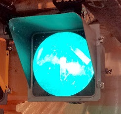
The lenses in 3M signals are unique in appearance because they're square, and they're even more unique in operation. The are made of glass and have a frensel pattern on the inside. This greatly magnifies the light going through it, which is very important for the masking process. The black mask is printed on the inside, outside, or on both sides of the lens, and determined what shape it shows when illuminated. Also unlike typical lenses, these could be rotated (in increments of 90°, of course) as needed.
Older lenses were formed and have round corners, while newer lenses were made completely square and then had the corners trimmed off. All lenses had a number stamped onto the outer side, possibly a production run number, while they also had one on the inner side, possibly showing part number or revision of the fresnel design.
Here is the list of known lenses for M-131 signals:
| Standard | Special |
Balls
Arrows (90°; Left, Right, or Upwards)
Diagonal Arrows (45°; Diagonal Leftward or Diagonal Rightward)
|
Light Rail Symbols
Canadian Shapes
Special Worded
|
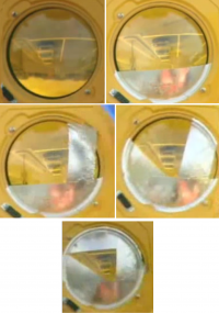
The masking process begins by looking straight through the optical limiter lens through the back of the signal. You can see the roadway that the signal is facing. Because it is a convex lens, the roadway will appear flipped 180°. With special optical masking tape that comes with the signal, you cover the areas of the road that you see through the lens for which you don't want the signal to be visible. Yes, it look all flipped around - but just like what you see through it is flipped, so will be the light that comes out, so it all works out in the end. The tape needs to be perfectly flat on the glass with no air bubbles to work properly. You can see videos explaining the masking process here (part 1) and here (part 2).
This works because the front lens has a fresnel pattern. This greatly magnifies the the light behind it. So instead of just looking like a partly lit lens, you see a zoomed-in part of that lens, either the lit or the masked part depending on where you are. Think of it like scrolling around on a zoomed in image.
PROGRAMMABLE VISIBILITY
- Viewing Area Limiting
With PV signals, you can limit the viewing area to anywhere from one approach at an intersection to a single lane at that approach. This is ideal for skewed intersections, where you could see the traffic signals of a different approach; turn signals, that cycle independently and might distract through traffic; divided intersections, where some lanes are signalized while others aren't; ramp metering, where each lane's signal cycles independently; and signals for bus/transit lanes, that might confuse vehicle traffic.
This is accomplished by applying optical masking tape to one or both sides of the optical limiter lenses. See more on the masking process above.
- Viewing Distance Limiting
Another feature of these signals is the ability to limit the distance of the visibility. This is ideal for multiple intersections that are very close to each other. Drivers might look ahead and see signals showing green at the wrong intersection, which can cause confusion and accidents.
Distance limiting is accomplished by applying optical masking tape to the bottom of the optical limiter lens (it's applied to the bottom, not the top, because the light flips 180° when it travels through the lens). See more about the masking process above.
HIGH VISIBILITY
- Fuller Indication
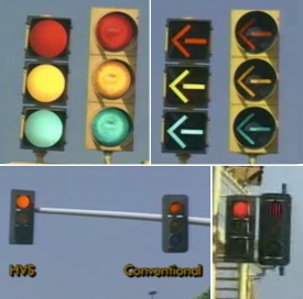
The 3M PV signal is also made to have fuller, clearer indications. The diffusing lens inside evenly distributes the lights, and the front lens has a fresnel pattern which magnifies the light and makes it appear even clearer.
There is no bulb "hot spot" on the lens. And since the whole lens is lit at its fullest, it can be seen better and from farther away (within the programmed visibility limits, of course).
- No Sun Phantoming
Sun phantoming is a condition with traffic signals where the sun shines in through the lens, reflects of the reflectors and shines back out the lens, making all indications appear to be lit even when they aren't. This can be a serious problem at large intersections. Because it would have to go through 4 lenses (including the cover of the PAR 46 bulb), into the bulb's small reflector and back out, there is little opportunity for that to happen.
- 3M signals were far more expensive than regular traffic signals. To achieve visibility limiting, many places opted to simply attach louvers on their existing signals. Though they couldn't limit the visibility as extensively, and they also block some of the light output even for the direction they face.
- 3M signals used PAR 46 bulbs, similar to those used in flood lights. They have shorter lives, higher temperatures, and are considerably more expensive than regular light bulbs.
- 3M signals were also heavy; a 3-section 3M weighs around 65 pounds, 15 heavier than a typical traffic light. This made installation difficult. 3M made it slightly better by having a terminal block in every section instead of just one, so they could wire it it out through any section depending on how they are installed.
- And, while 3M was the first to create such a signal, in more recent years (as early as 1997) they have had some competition. McCain Traffic and Intelight (previously OptiSoft) both make programmable visibility signals.
The McCain PV Signal was developed in early 2000s, and is nearly identical in design to 3M PV signals. Many parts are interchangeable with the M-131 as well, including the Light Shield, Diffusing Lens, Masking Lens, Bulbs (LED or Incandescent), and Wire Terminals. McCain's PV signals use round lenses (overcoming one of the drawbacks to 3M's square lenses) and they use standard 12" visors which makes them easier to replace.
Intelight signals are very different in design but utilize the latest LED technology, which makes far better in that regard.
This competition is part of the reason behind declining sales which led to 3M dropping out of the traffic signal industry in 2007.
All 3M signals were given a serial number. A small decal, about 1" x 2" in size, was placed on the back of the housing inside the back door. A serial number was stamped onto this decal. Many lights were given sequential numbers for each head - i.e. Red would be "100", Yellow then "101", and Green "102". There were at least four versions of the decal, with the two common being known as the 'Old Style' and 'New Style'.
A list of known serial numbers owned by collectors can be found here.
M-131R Bimodal (Ball/Arrow) Signal
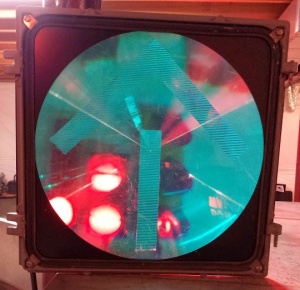
This is a unique signal; nothing quite like it has ever been made. It features what appears to be a ball indication from a distance, but as you get closer, it turns into an arrow.
Here's how it works:
The portion of the ball surrounding the arrow on the lens features the normal 3M fresnel pattern to it, which magnifies the light. The arrow part, however, has a prismatic pattern, which reflects light out in every direction. Because of this, where the signal is masked off like normal and you can't see the ball, you can still see the arrow.
Unlike the PV signals, you don't want to limit the visibility; in fact, the purpose of this is to extend it (arrows can sometimes be difficult to see from far away, which is a problem this signal solves). Instead, the masking is done just to set the point of proximity at which the indication appears to change. This is done by applying masking tape to the top of the optical limiter lens, so that direct light does not shine out as you get close to the signal (since the light flips 180° as it passes through). Since only direct light can pass through in the ball area, that part appears dark. The arrow portion, with its prismatic texture, takes the light coming from the bottom of the lens and sends it out in all directions, so it can still be seen.
From far away, when the arrow and surrounding area are lit, it looks like a normal ball (though you may be able to see the faint outline of an arrow).
The housing of these signal sections are identical to the M-131 signals, except that they have different connectors. To get the right viewing angle, these signals must be mounted with a tilt angle of 0°. These connectors are at 0° and can't be adjusted.
Because of the specific horizontal-lined texture in the arrow, the lens would not work correctly if rotated (except for in 180° increments. Different lenses had to be made for turn arrows and vertical arrows. Here is a list of the known versions that were made:
- Green Upwards Arrow + Ball
- Red Turn Arrow + Ball
It is likely that left/right, upwards, left diagonal, and right diagonal versions in red or green could be custom-ordered, though none other than those listed are known to exist (most likely not in yellow for obvious reasons). 3M only advertised the green upwards arrow version, but the red turn arrow version exists (albeit rare) in California.
M-133 Dual-Indication (Green/Yellow) Programmable Visibility Signal
The 3M "dual indication" signal is what would generally be called a Bimodal arrow by most people in the traffic industry. In one section, it can switch between a green and yellow arrow. While this would be accomplished with fiber-optics in normal signals, that would not work for programmable visibility signals, so 3M's system was much more complicated.
The M-133 housing was identical to that of the M-131 signal, with the exception of an extra attachment on the side that houses a motor. The signal is masked and the tilt is set in exactly the same way. The only difference is the way it functions.
The front arrow lens is clear. Insides the housing, where there would normally be empty space, is a round lens held in place by wheels that are attached to the motor. Half of it is green and half of it is yellow. There is a black cover behind the bottom half of the lens, so only one color is exposed at a time. When the protected turn phase starts, the light turns on with the green half of the lens showing. When the phase is over, the motor kicks in and quickly spins the lens so the yellow have is showing. The transition is fast and fairly smooth. After the yellow clearance phase is completed, the light goes out and the motor spins the lens (at a slower speed) back into the green position, awaiting the next arrow phase.
"Doghouse Bimodal Signal"
This signal had the same function as a doghouse, but in a 3-section signal. The top section was a red ball, the middle section was a 'maunual' bimodal yellow ball/arrow, and the bottom section was a 'manual' bimodal green ball/arrow. The 'manual' bimodal was different from the M-131R bimodal because it switched from arrow to ball manually, not based on proximity.
Nothing is known about have it worked. It likely never made it past the experimental phase, and was never sold on the market.
Full Pedestrian Signals (12")
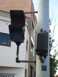
M-131 Programmable Visibility Pedestrian Signal
This M-131 PV pedestrian signal is exactly the same as the M-131 vehicle signal, except with different lenses.
Lenses
The following lenses were available for these signals:
- Portland Orange HAND Symbol
- Lunar White MAN Symbol
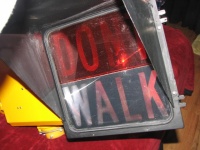
- Portland Orange "DONT WALK"
- Lunar White "WALK"
- Red "DONT WALK"
- Green "WALK"
M-132 Dynamic Programmable Visibility Pedestrian Signal
---IN PROGRESS---
Vehicle Signal Adapters (8")
SA-130A Programmable Visibility Adapter
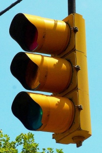
3M never made full 8" traffic signals; however, they did make programmable visibility attachments that can be put on any normal 8" housing. They are mounted in the door, taking the place of the lens & visor, but it utilizes the existing reflector and bulb. A page showing how these attachments are installed can be found here.
The interior of these attachments is similar to that of 3M's 12" signals. It has a regular lens at the outside end, and a diffusing lens on the inside end. Unlike the 12" signals, though, there is no optical limiter lens (a clear lens where the optical masking tape is applied to limit the area of visibility), so the optical masking tape is put directly on the diffusing lens. It still works in the same way. Finally, on the end of these adapters, a small visor is attached. Without the visor, these adapters are about the same size as normal tunnel visors.
Lenses
- Red Ball
- Yellow Ball
- Green Ball
- Green Arrow
(Though they may have been a special order option, no yellow or red arrows are known to have existed.)
Vehicle Signal Internal Converters (12")
M-150 Lens/Reflector System
The 3M M-150 Lens & Reflector System was created by 3M to give regular 12" traffic signals some of the M-131 signal's features.
The M-150 is installed almost exactly like a modern LED module. The signal's original socket, reflectors & lens would be removed; the M-150 unit has all of those in it. The wires that went to the original socket are rewired to the back of the unit. It is then fitted into the door just like the lens was.
The front extended part is a dual diffusing lens (dome-shaped on the inside, cylinder-shaped on the outside). These inserts offered the High Visibility feature of the M-131 signal (having a fuller, brighter & clearer indication, compared to that of a typical incandescent signal). It did not have the Programmable Visibility feature, because the masking would have to be applied too close to the light source to have the proper effect. These were available in green, yellow, and red balls, and likely all color arrows as well.
DISCONTINUATION:
3M discontinued these early on, because they caused an effect called 'sun phantoming', which occurs when the sun shines through the lens and is reflected back out by the reflector, making it look like all indications are lit.

PC-310 Signal Intensity Control
Nothing is known about this device. It was likely never sold on the market.
Because of the name, it may possibly have been a system for similar to the M-131's photocell dimmer unit, which changes the brightness of the signal depending on the brightness outside.
Signal Enlargers
Signal enlarges are attachments mounted on a signal door that expand to fit a larger lens. Around the early 60s, larger signal indications were becoming more popular because visibility was becoming a greater concern. Installing enlargers on a signal was cheaper and easier than replacing it.
3M made 3 lines of signal enlargers; for vehicle signals, round-lens pedestrian signals, and square-lens pedestrian signals. They were all reprimanded for not being built to 3M's strength & quality standards; they were made of thin, lightweight folded sheetmetal with many unsealsed slots on the corners and along the sides. They were mounted in the place of a signal's visor, using the exact same attachments.
Vehicle Signal to Vehicle Signal


These were made to convert the display of typical 8" signals to that of a 12" signal.
SA-812
Patented on December 17 1973, this enlarger unit converts a typical 8" signal indication to a 12" indication. The enlarger mounts where the visor would go on the signal's door. It is essentially a box that expands around an 8-inch lens to fit a door with a 12-inch lens.
The signal's original 8-inch lens is replaced with a glass diffusing lens. The enlarger is attached in the place of the visor using the visor's screws. It is octagon-shaped where it attaches to the door; as it extends outward, the slanted sides (which are triangle-shaped) become the corners of the square-shaped front. A square lens slides into the lens holder/front door of the unit, which has a 12" circular hole for the indication to shine through. The door then simply slides into place on the front of the enlarger.
With this setup, the light shines through the 8" lens, into the enlarger and out the 12" lens, generating a larger and more visible indication with the same amount of light and without having to replace the signal.
3M specifically noted that these enlargers would not fit Eagle Durasig signals or any TSI signals. They offered special clips needed when mounting on Crouse-Hinds signals.
The name of this product means "Signal Adaptor - 8 inch to 12 inch"
SA-810
If enlargers need to be used on two consecutive sections of a signal (for example, the 2 green indications on a 4-section R–Y–G–GA signal), there would not be enough space. The SA-812 12" enlarger extends slightly over both sections around it in order to... well, enlarge... and you would not be able to fit a second one beneath it.
That is what the SA-810 is for; it is designed specifically to fit under an SA-812. It is almost exactly the same as the SA-812, except that it bends down at the top (instead of up) to fit beneath and match the curvature of the other one. Because of the height limitation, the lens is only 10"x12". And due to that irregular size, they were only available with green left or right arrows. Horizontal arrows are the only indications that would be able to fit while remaining the correct size.
The name of this product means "Signal Adaptor - 8 inch to 10 inch"
Vehicle Signal to Pedestrian Signal
Though the 3M catalog specifically says these "are adapters to enlarge 8" vehicle signals to 12" pedestrian signals", they were most likely designed for round-lens WAIT-WALK pedestrian signals (which used the same housing as vehicle signals).
SA-812DW
This enlarger uses the same body as the SA-812 with the lens & door of a SA-912.
The name of this product means "Signal Adapter - 8 inch to 12 inch pedestrian, DONT WALK"
SA-810W
This enlarger uses the same body as the SA-810 with the lens & door of a SA-910.
The name of this product means "Signal Adapter - 8 inch to 12 inch pedestrian, WALK"
Pedestrian Signal to Pedestrian Signal

If you notice, this image has 2 mistakes; the dotted signal behind it is a vehicle signal (instead of a pedestrian signal), and the back of the enlarger has an octagon shape (instead of square).


The signal has since been removed.
These were made to convert the display of typical 9" pedestrian signals to that of a 12" pedestrian signal.
SA-912
This enlarger is for the DONT WALK section of a pedestrian signal. The SA-910 is for the WALK section.
The enlarger mounts where the visor would go on the signal's door. It is essentially a box that expands around a 9-inch lens to fit a door with a 12-inch lens.
The signal's original 9-inch lens is replaced with a clear or colored plastic diffusing lens. The enlarger is attached in the place of the visor using the visor's screws. It is square-shaped at both ends. A square DONT WALK plastic frensel lens with red 4½" lettering slides into the lens holder/front door of the unit, which acts as a frame for the lens. There is a lip around the inside edge of the door frame, to which the new visor attaches. The door then simply slides into place on the front of the enlarger.
With this setup, the light shines through the diffusing lens, into the enlarger and out the 12" lens, generating a larger and more visible indication with the same amount of light and without having to replace the pedestrian signal.
3M offered specific versions of these adaptors with slightly different attachments to fit Marbelite and Econolite pedestrian signals.
The name of this product means "Signal Adaptor - 9 inch to 12 inch"
SA-910
This enlarger is for the WALK section of a pedestrian signal. The SA-912 is for the DONT WALK section.
This enlarger section has a 10"x12" lens. It is smaller because it needs to fit beneath the SA-912 adaptor on a pedestrian signal. The SA-912 (DONT WALK), which is a full 12"x12", extends slightly over the WALK section. In order to match the curvature, the top of this adaptor bends downward, instead of upward like the SA-912. Other than that, they are exactly the same.
The DONT WALK indication needs to be largest because it has two lines of text, and the WALK indication only has one. In a normal signal, the DONT WALK and WALK lenses are the same size, and the WALK has blank space on the top and bottom. That extra space could be cut off and the WALK indication would remain the correct size, which is essentially what was done with these.
Like the SA-912, this adaptor is attached where the visor would go on a signal, using the visors screws. The original lens is replaced with a clear or colored plastic diffusing lens. The outer lens, a plastic frensel lens that says WALK in 4½" white lettering, is displayed on the front of the adaptor.
The name of this product means "Signal Adaptor - 9 inch to 10 inch"
Signs
Reflective
3M is a leader in the industry of reflective signage and sheeting, in addition to many other road products. You can see them here: http://solutions.3m.com/wps/portal/3M/en_US/NA_roadway/safety/productcatalog/~/Roadway-Safety?N=3293989410+7566298+7584153+8695783+8694413&rt=r3
Electronic
3M made a bi-modal, time-programmable sign lighted sign for roadways. Little is known about them.
